

Complete Guide to Compressed Air Treatment: Inline Filters and Refrigerated Dryers

Industrial compressed air filters and refrigerated dryers form the core treatment cascade required to eliminate atmospheric particulates, compressor lubricant aerosols, and liquid moisture from pneumatic supply lines. To achieve reliable air purification, system designers pair particulate inline filters to remove solid debris down to 1 micron, high-efficiency coalescing filters to strip oil aerosols down to 0.01 mg/m³, and refrigerated air dryers to suppress the pressure dew point to +3°C (+37.4°F). This combined approach meets ISO 8573-1:2010 air quality standards, protecting air-operated machinery, automated valves, and end-use manufacturing processes from severe corrosion, pipe scale buildup, and product contamination. EL-AIR Systems supplies complete air treatment components—engineered and manufactured by EL-AV Compressors—including EF Series inline filters, ELRD Series refrigerated dryers, and genuine EL-AV replacement filter elements to ensure continuous peak performance and minimal pressure drop across North American manufacturing facilities.
Mapping Air Quality Requirements to ISO 8573 Guidelines
Designing an efficient compressed air treatment system begins with establishing the exact air purity standard required at point-of-use operations. Industrial manufacturing protocols rely on ISO 8573-1:2010 as the baseline standard for classifying air purity across three primary contaminant types: solid particles, humidity/water content, and total oil content (liquid, aerosol, and vapor).
Air quality specifications are written as three class numbers denoting [Particles : Water : Oil]. For example, a system rated as Class 1.4.1 delivers Class 1 particulate filtration, Class 4 pressure dew point control, and Class 1 oil removal. Note that for solid particle concentration, ISO Particle Classes 1 through 5 strictly prohibit any particles larger than 5.0 µm in diameter. Understanding these exact threshold limits prevents both under-filtering (which causes equipment failure) and over-filtering (which introduces unnecessary pressure drop penalties and elevated energy costs).
| ISO 8573-1:2010 Purity Class | Solid Particles (Max counts/m³ for 0.1-0.5 µm / 0.5-1.0 µm / 1.0-5.0 µm) | Water Pressure Dew Point (°C / °F) | Total Oil Concentration (Liquid + Aerosol + Vapor) |
|---|---|---|---|
| Class 0 | User or supplier specified (More stringent than Class 1) | User or supplier specified (More stringent than Class 1) | User or supplier specified (More stringent than Class 1) |
| Class 1 | ≤ 20,000 / ≤ 400 / ≤ 10 | ≤ -70°C (-94°F) | ≤ 0.01 mg/m³ |
| Class 2 | ≤ 400,000 / ≤ 6,000 / ≤ 100 | ≤ -40°C (-40°F) | ≤ 0.1 mg/m³ |
| Class 3 | Not specified / ≤ 90,000 / ≤ 1,000 | ≤ -20°C (-4°F) | ≤ 1.0 mg/m³ |
| Class 4 | Not specified / Not specified / ≤ 10,000 | ≤ +3°C (+37.4°F) | ≤ 5.0 mg/m³ |
| Class 5 | Not specified / Not specified / ≤ 100,000 | ≤ +7°C (+44.6°F) | Class X / Unclassified (> 5.0 mg/m³) |
Typical application groupings commonly align with specific ISO target classes:
- General Plant Air & Pneumatic Tools (Class 4.4.4): Requires general particulate filtration down to 5 microns, refrigerated drying to prevent free standing liquid in main headers, and basic oil separation.
- Automotive Painting, Robotics & Precision Controls (Class 1.4.1 or Class 2.4.2): Demands high-efficiency coalescing filtration down to 0.01 micron to prevent silicone or oil spot defects in coatings, combined with refrigerated drying to +3°C PDP.
- Pharmaceutical, Food Packaging & Cleanroom Pneumatics (Class 1.2.1 or Class 1.1.1): Requires sub-zero pressure dew points (-40°C to -70°C) provided by desiccant adsorption dryers, coupled with multi-stage coalescing and activated carbon vapor removal. Refrigerated dryers cannot cool air below freezing without ice fouling, restricting their rating to Class 4 or Class 5 (+3°C to +7°C).
Sizing Coalescing and Particulate Inline Filters for Peak Flow
Particulate and coalescing inline filters function through mechanical trapping mechanisms: direct interception, inertial impaction, and Brownian diffusion. Dust filters collect dry solid particles on outer media surface fibers, while coalescing filters pass compressed air from the inside of the element matrix to the outside, forcing fine oil aerosols to merge into larger droplets that gravity drains into the housing bowl.
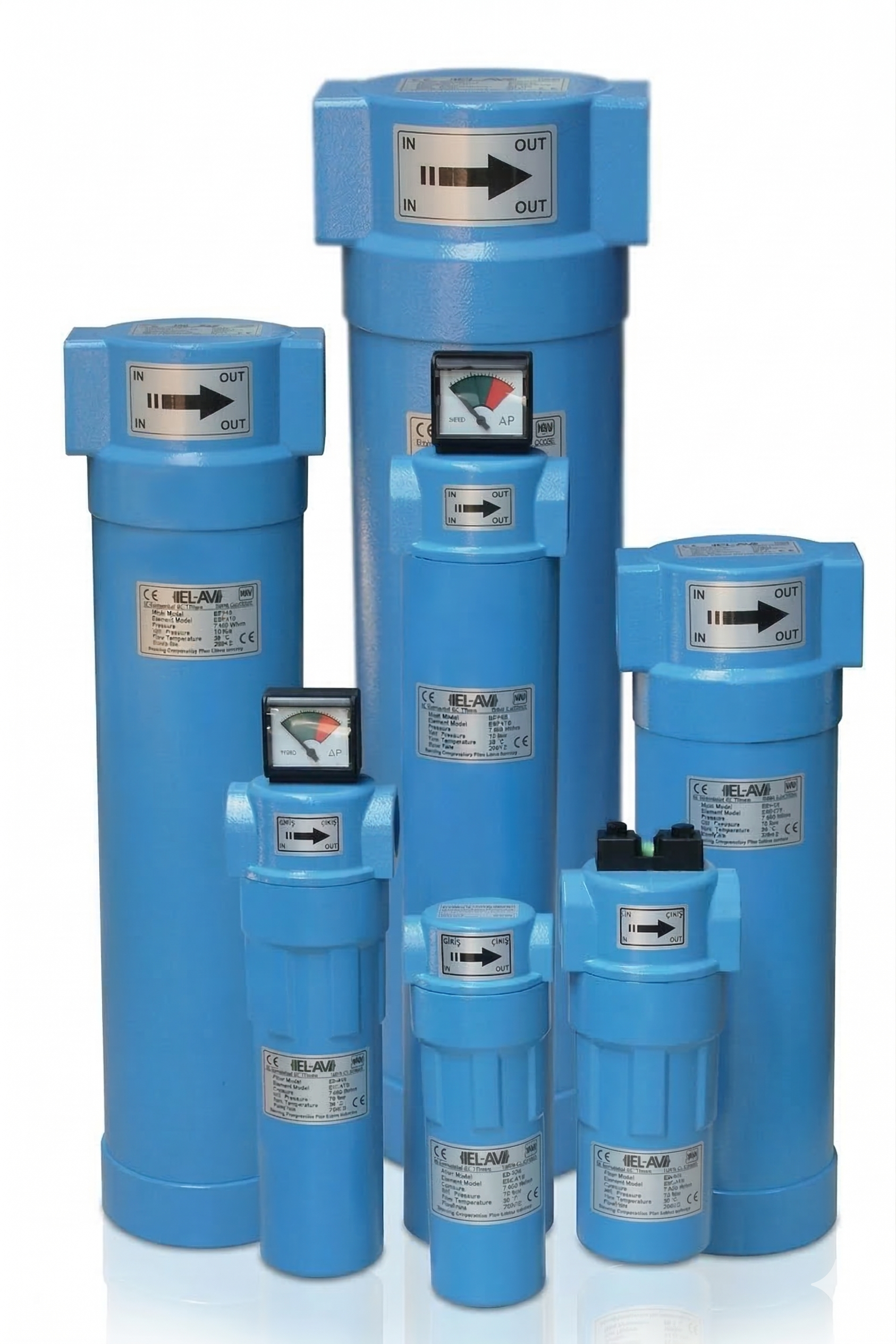
When sizing inline filter housings and replacement elements, system engineers must account for maximum volumetric flow (CFM) at minimum operating pressure rather than nominal compressor output. Operating at lower pressures increases air velocity through the filter media, reducing residence time and degrading filtration efficiency while dramatically raising differential pressure loss.
- Peak Flow Calculation: Always size filter housings for the system's maximum peak demand flow (SCFM) corrected for operating pressure.
- Allowable Pressure Drop: Clean filter elements typically exhibit an initial differential pressure of 1.0 to 1.5 PSI. Elements should be replaced when pressure differential reaches 8 to 10 PSI or during annual preventative maintenance to prevent media rupture and excess kilowatt draw at the compressor.
- Filter Element Selection: To maintain optimal filtration efficiency and prevent pressure drops, always use genuine EL-AV EE Series replacement elements engineered specifically to match your inline filter housings.
Integrating Refrigerated Air Dryers into High-Humidity Piping Loops
While inline filters efficiently capture liquid water droplets and oil aerosols, they cannot remove water vapor. As compressed air cools inside plant distribution piping, water vapor condenses into liquid, causing rust, pipe scale, air tool failure, and washed-out greases. A refrigerated air dryer cools incoming compressed air via a closed-loop refrigeration system, condensing gaseous moisture into liquid water that is automatically purged through a condensate separator.
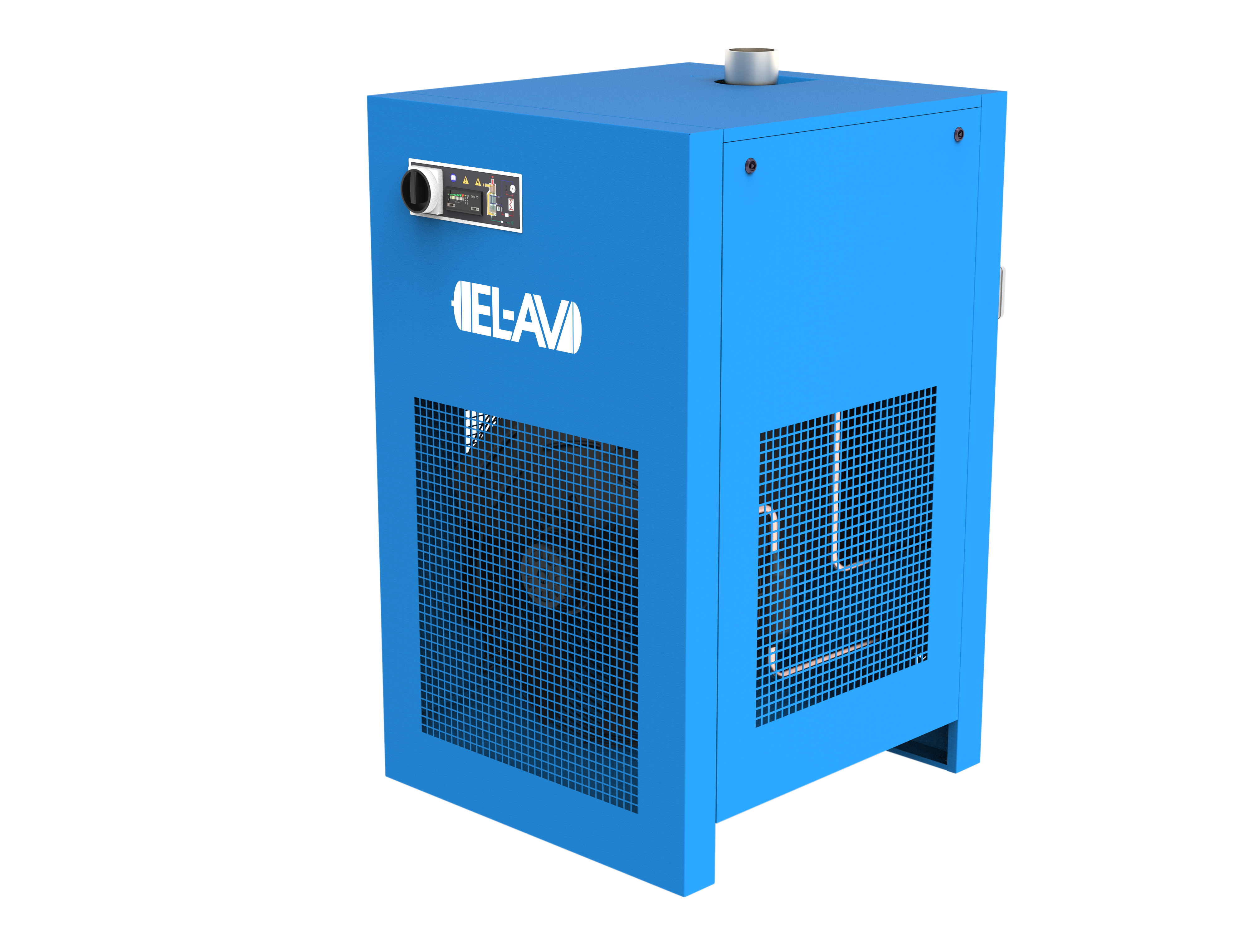
Refrigerated dryers are engineered to yield an ISO 8573-1 Class 4 pressure dew point (+3°C / +37.4°F) to Class 5 (+7°C / +44.6°F). Because their operating principle relies on mechanical refrigeration, they cannot reach sub-freezing dew points (Class 1 to 3) where condensed moisture would freeze on heat exchanger surfaces.
A critical rule of air thermodynamics states that saturated compressed air holds exponentially more water at higher temperatures: for every 10°F (+5.6°C) increase in inlet air temperature, the mass of water vapor entering the dryer increases by approximately 35%. If the compressor aftercooler fails or becomes fouled with ambient dust, the thermal overload on the dryer can exceed rated capacities, driving liquid moisture directly into downstream filters.
Recommended System Architecture: The 6-Step Installation Sequence
To optimize air quality, protect air treatment equipment, and achieve maximum energy efficiency, EL-AIR recommends installing products engineered by EL-AV Compressors in the following strict 6-step sequence:
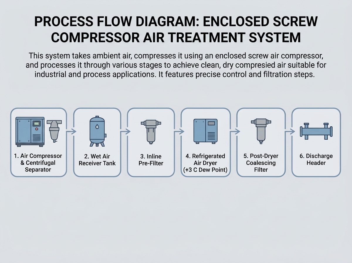
- Step 1: Rotary Screw or Piston Air Compressor immediately followed by an inline Centrifugal Moisture/Droplet Separator to remove heavy bulk water droplets from the high-temperature discharge air.
- Step 2: Wet Air Receiver Tank fitted with a Smart Electronic Zero-Loss Drain. The receiver tank buffers pressure fluctuations and provides radiant cooling to strip bulk moisture before air flows downstream.
- Step 3: Inline Pre-Filter (rated 1.0 to 0.1 micron, equipped with a Smart Mechanical Float Drain) positioned directly before the dryer. This pre-filter intercepts solid particles and bulk liquid oil to protect the heat exchanger surfaces of the dryer from fouling.
- Step 4: ELRD Series Refrigerated Air Dryer achieving a stable +3°C (+37.4°F) pressure dew point (ISO Class 4 moisture control).
- Step 5: Post-Dryer Filtration Set consisting of a 0.01 micron high-efficiency coalescing filter (and an optional 0.003 mg/m³ activated carbon vapor filter for odor and oil vapor removal), fitted with a Smart Mechanical Float Drain to catch microscopic oil aerosols.
- Step 6: Discharge Header connecting to smooth-bore plant distribution pipes and hoses supplying clean, dry air to point-of-use equipment.
Drain Valve Placement and Condensate Separation Best Practices
Even the most advanced filtration matrix and refrigerated dryer fail if liquid condensate accumulates in filter bowls, receiver tanks, or dryer heat exchangers. Automated condensate management requires selecting the appropriate drain valve technology based on the location and volume of liquid generation across the plant network.
Drain Valve Differentiation and Selection
EL-AIR recommends distinct drain technologies based on condensate volume and power accessibility:
- Smart Electronic Zero-Loss Drains for High-Volume Points: Install sensor-managed electronic zero-loss drains (or dedicated timer-activated electronic drain valves) on air receiver tanks and main dryer separators where large volumes of condensate collect. Electronic zero-loss drains discharge liquid only when internal liquid sensors detect accumulated condensate, eliminating air waste.
- Smart Mechanical Float Drains for Filter Housings: Install smart mechanical float drains inside pre-filter and post-filter bowls. Mechanical float drains operate automatically via liquid buoyancy, delivering power-free, zero-loss liquid evacuation right at the bowl without requiring electrical wiring.
Environmental Condensate Management
Because condensate discharged from lubricated rotary screw compressors contains emulsified oil, discharging raw condensate directly into storm or sanitary sewers violates regional environmental regulations. Piping all drain outlets directly into multi-stage oil-water separators splits oil from clean water, enabling compliant environmental disposal while protecting operational uptime.
Whether upgrading a single inline filter or engineering a full plant air treatment system, ensuring correct component staging, sizing, and condensate discharge protects your operational uptime. Contact our support team today for targeted air treatment solutions.
Frequently Asked Questions
What ISO 8573-1 air quality class can a refrigerated air dryer achieve?
A refrigerated air dryer typically achieves ISO 8573-1 Class 4 (+3°C pressure dew point) to Class 5 (+7°C pressure dew point). Because mechanical refrigeration cannot cool air below freezing without ice forming on the heat exchanger, sub-zero pressure dew points (Classes 1 to 3) require a desiccant dryer.
What is the difference between a particulate pre-filter and a coalescing inline filter?
A particulate pre-filter traps dry solid debris like dust and rust particles from entering the system. A coalescing filter forces air through a fine fiber matrix from the inside out to coalesce liquid oil mist and aerosols into larger droplets, which drain away by gravity.
How often should compressed air filter elements be replaced?
Filter elements should be replaced when the differential pressure reaches 8 to 10 PSI or during annual scheduled preventative maintenance, whichever comes first, to prevent media rupture and excessive compressor energy consumption.
Why is an automatic condensate drain required on air treatment equipment?
As compressed air cools inside receiver tanks, dryers, and filter bowls, water vapor condenses into liquid water. Automatic condensate drains purge this accumulated liquid before it re-enters downstream piping and damages pneumatic machinery.

